

LTspice is a SPICE based analogue circuit simulator from Analog Devices (originally Linear Technology), and the most widely used SPICE software in the industry. It is free and ships with many models, but those are either generic or specific to Analog Devices parts. For anything else, you need to import the manufacturer’s model.
This guide covers importing PSpice and TINA-TI models. If the model contains a .SUBCKT definition, the import is straightforward.
Importing from PSpice
This is the easier of the two.
-
Download the PSpice model from the manufacturer’s website. We use the TI TMUX6212 as the example.

-
The download contains several files. The only one you need is the
.libfile, hereTMUX6212.lib.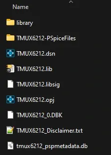
-
Open the
.libfile in LTspice.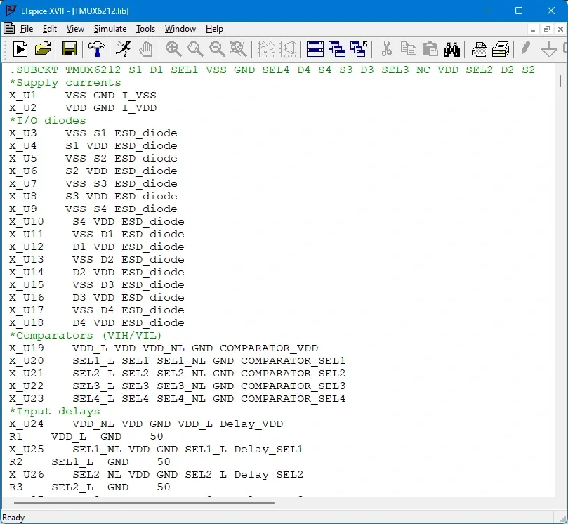
-
Select the component name next to
.SUBCKT.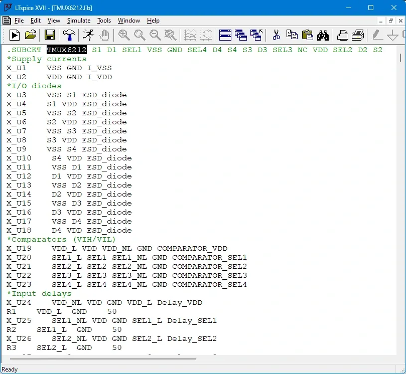
-
Right click and choose Create Symbol.
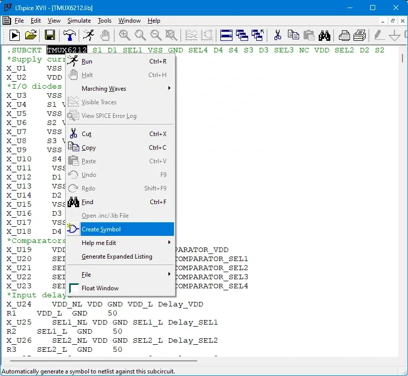
-
Click Yes.
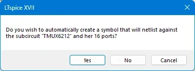
-
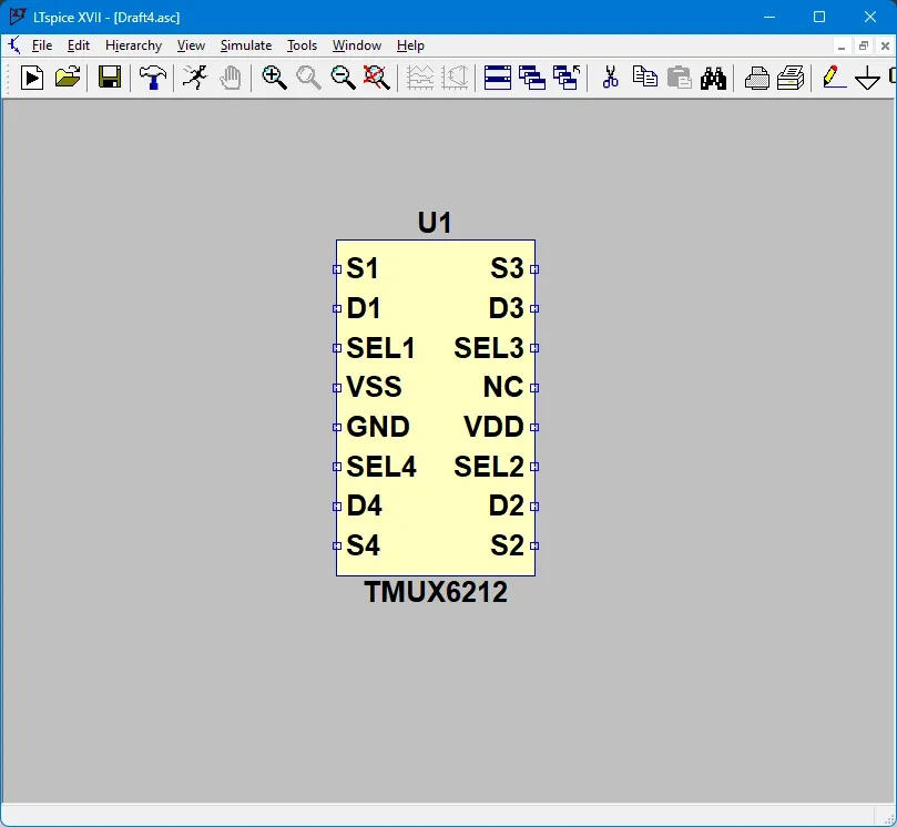
LTspice generates the symbol, with a
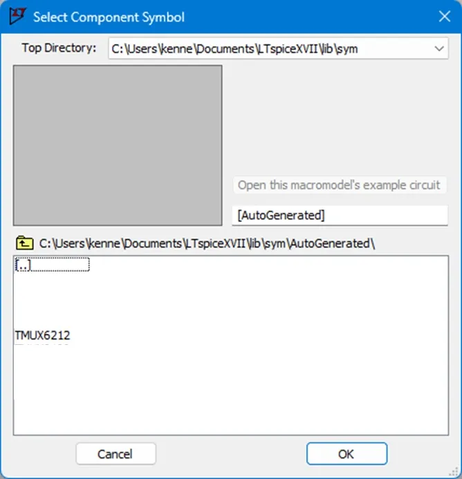
.asyextension, in its AutoGenerated folder (for exampleC:\Users\user\Documents\LTspiceXVII\lib\sym\AutoGenerated; the path depends on your settings).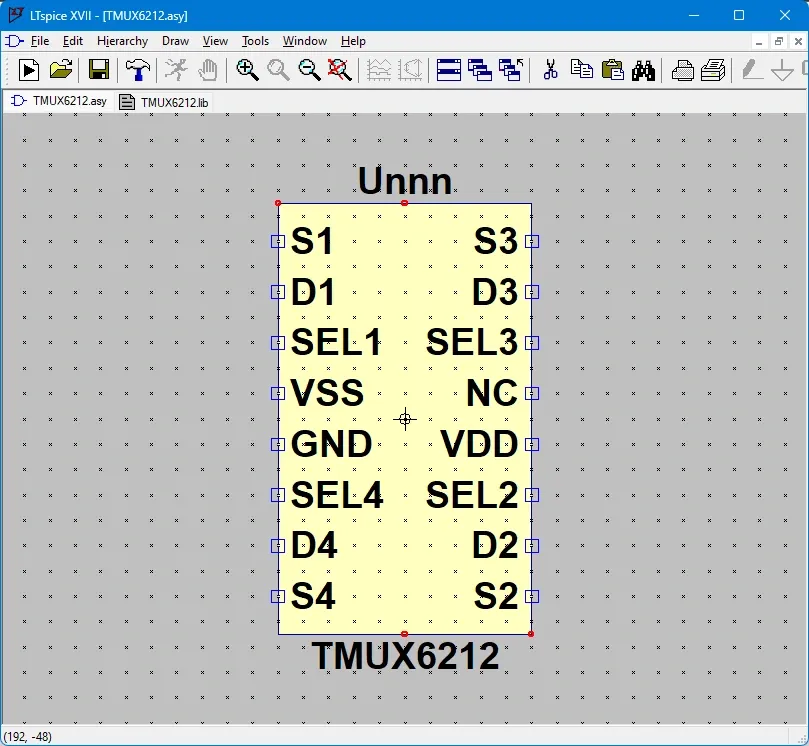
-
Rearrange the pins if you like, and save the symbol.
-
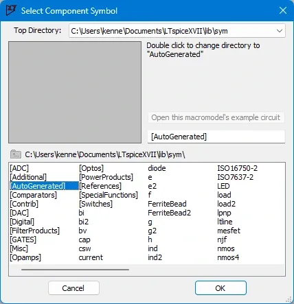
Add the symbol to your schematic from the component library. Test the model before relying on it; for this part, simple checks of the logic, switching and power rails are a good start, and you can go further with resistance and bandwidth.
Importing from TINA-TI
You will need TINA-TI installed.
-
Product pages often offer a TINA-TI reference design to download. We use the MUX36D04 as the example.

-
The download gives you
sbom969a.tsc. Open it in TINA-TI.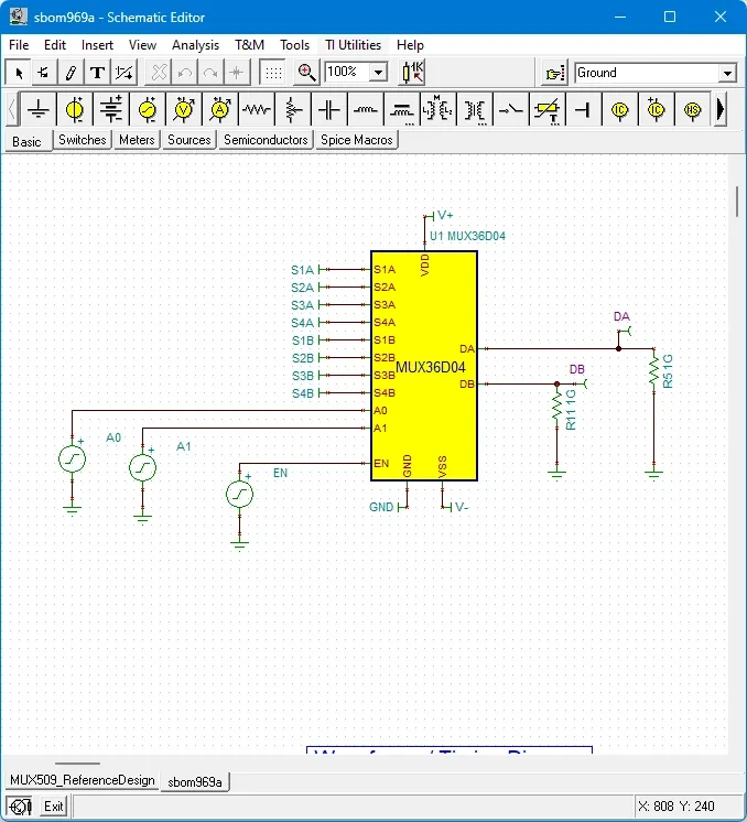
-
Right click the model and choose Enter Macro.
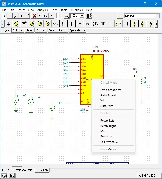
-
The macro file opens. Use Save As to create a
.cirfile.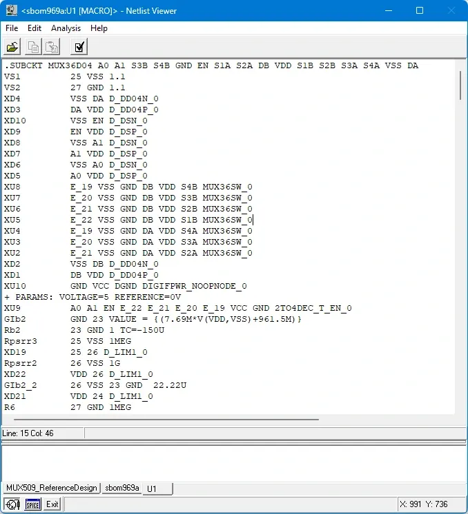
-
Open the
.cirfile in LTspice.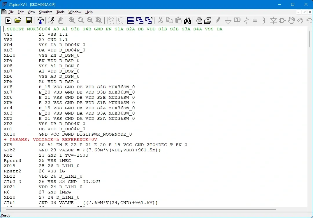
-
Select the component name next to
.SUBCKT, right click and choose Create Symbol.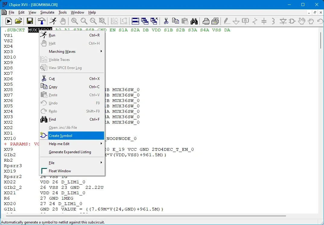
-
Click Yes.
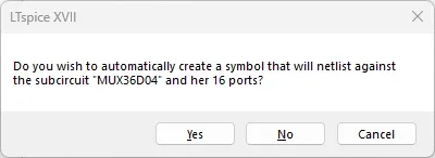
-
LTspice generates the
.asysymbol in the AutoGenerated folder, as before.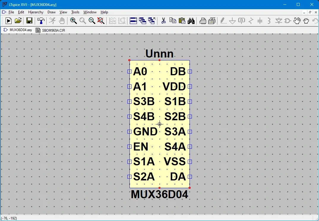
-
Rearrange the pins if you like, save, then add the symbol to your schematic and test it.
Making the model portable
Sometimes you want to share a simulation, and the absolute path to the model gets in the way.
-
Import the model using either method above.
-
Open the symbol file from the AutoGenerated folder in a text editor.
-
Remove the absolute path from the model file line. In our example it becomes
SYMATTR ModelFile TMUX6212.lib.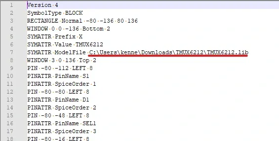
-
The symbol now looks for the model in its own folder. Copy the model file (
.libor.cir, depending on where it came from) next to the symbol. -
Keep the schematic, symbol and model file in the same folder. By default the LTspice component dialog only shows two places: your schematic’s folder and the installed component library.
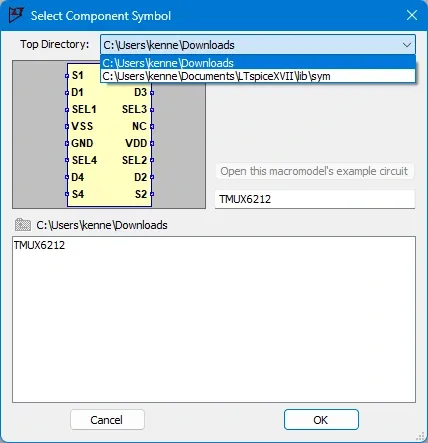
We hope this helps with your simulations.
Sources: LTspice, Analog Devices; LTspice XVII introduction, LTwiki.