

These are the waveforms of a zero voltage switching (ZVS) inductive heating circuit, and its thermal profile in operation.
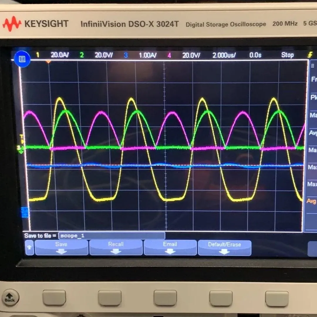
Fig 1 · The switching voltages
A typical buck regulator is hard to design when the input and output voltages are far apart. A large drop increases switching losses and limits the switching frequency, because the MOSFET carries high current and high voltage at the same time as it turns on and off. Designers often add a second regulation stage to cope: going from 19 V to 1.8 V may need two stages, which costs board space and larger filter components.
Zero voltage switching
ZVS lets a regulator switch faster at a higher input voltage and a lower voltage drop. It uses PWM or a resonant technique with an extra, separate phase in the switching signal, so the switch changes state when the voltage across it is close to zero. Switching “smoothly” like this avoids most of the switching losses of conventional PWM timing.
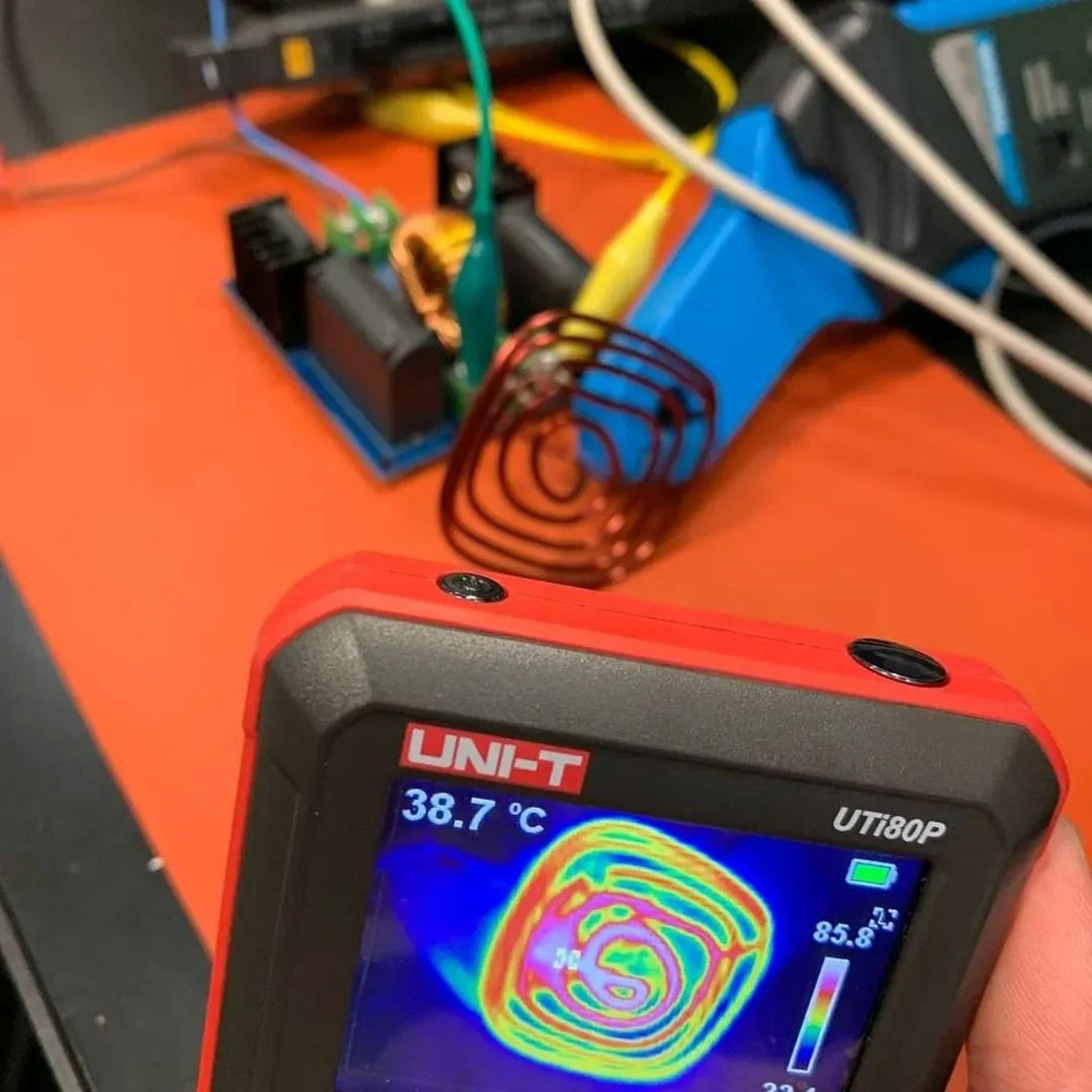
Fig 2 · The coil heating up
ZVS as an inductive heater
One use of a ZVS circuit is as an inductive heater. In this project, our client supplied their own coil and asked us to measure how efficiently the ZVS circuit drove it. Because the ZVS circuit is resonant, the coil’s inductance directly sets the operating frequency.
Calculating the resonant frequency
The resonant frequency of the circuit is:
f = 1 / (2π √(LC))
where L is the coil inductance and C is the capacitance designed into the ZVS circuit.
Our evaluation
The coil measured about 1 µH at 100 kHz, and the ZVS circuit has two 0.33 µF capacitors in parallel, 0.66 µF in total. That puts the resonant frequency at around 196 kHz, which matches the frequency we probed on the circuit closely.
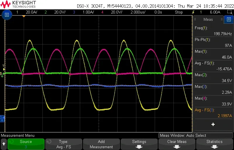
Fig 3 · Yellow: coil current. Green: coil voltage at one end. Red: coil voltage at the other end. Blue: system current
The capture shows why it is called zero voltage switching: the switch only changes state when one end of the coil reaches 0 V (green and red). A typical MOSFET buck regulator has much more overlap during switching, and that overlap is lost power.
Gate switching voltages
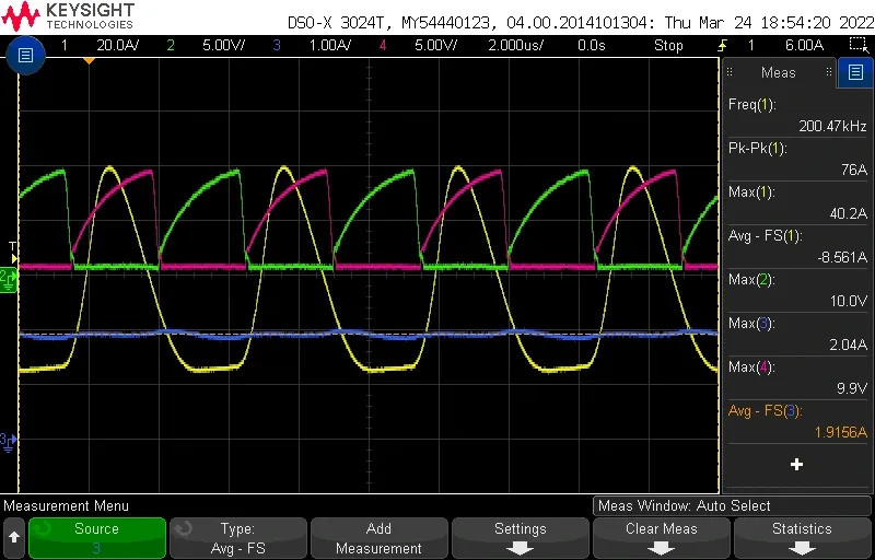
Fig 4 · Yellow: coil current. Green: MOSFET 1 gate. Red: MOSFET 2 gate. Blue: system current
From the gate voltages, the MOSFETs may not be reaching saturation. We can only infer this, as the circuit is rated for higher current and the MOSFET part number was not available. Without saturation, the MOSFET cannot pass the maximum current into the coil, which limits heating. Running in the linear region does keep the MOSFET relatively cool and prevents thermal runaway, so tuning a circuit like this is a trade between current capability and heat. It is also why the MOSFETs need heatsinks.
For this circuit, our recommendation to the client was to increase the coil inductance. That lowers the resonant frequency and lets the MOSFETs spend longer in saturation, improving heating.
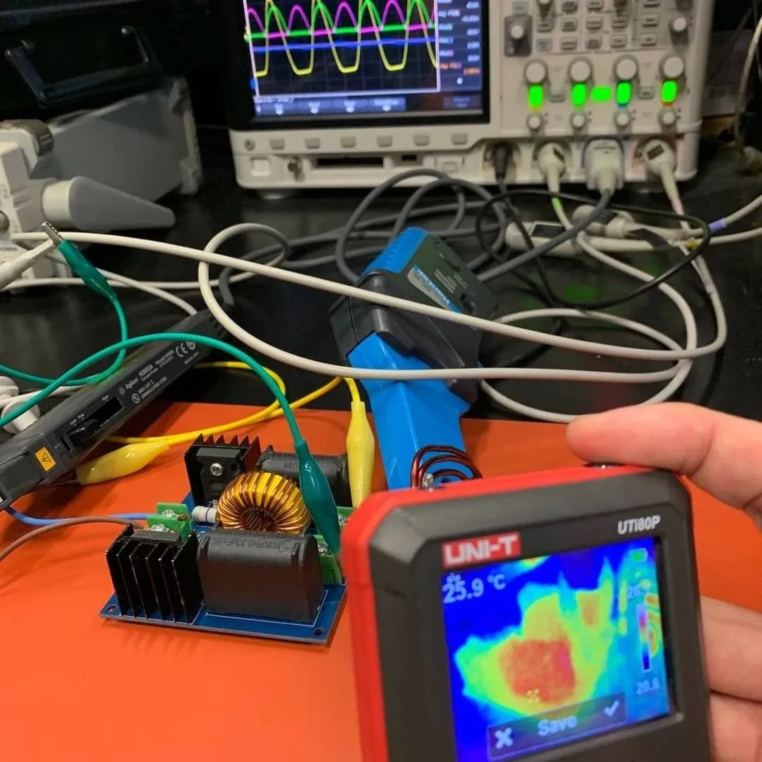
Fig 5 · With heatsinks fitted, the MOSFETs stay relatively cool; the capacitors heat up under the load and switching